7.1 Fusion 360
What is Fusion 360?
Fusion 360 is a 3D Design, CAM, and CAE tool from Autodesk. It is a cloud-based tool that allows you to design, simulate, and manufacture your robot. It is available for free to all FIRST Robotics Competition teams. Students and Mentors should sign up for a free account at https://www.autodesk.com/education/edu-software/overview?sorting=featured&filters=individual. After you setup or activate the Fusion 360 Educational access you should download it from https://www.autodesk.com/products/fusion-360/students-teachers-educators. You can also download the Fusion 360 app for your mobile device from the app store.
What are some of the Pros and Cons of Fusion 360 vs. other CAD tools?
| Pros | Cons |
|---|---|
| Free for all FIRST Robotics Competition teams | |
| Cloud-based | |
| Available on Windows & Chromebooks | |
| Collaboration is easy | |
| File Viewer available for iOS and Android | |
| Cloud-based | |
| Teams Setup can be confusing |
How do I get started with Fusion 360?
1. Download Fusion 360
Download Fusion 360 from https://www.autodesk.com/products/fusion-360/students-teachers-educators. You can also download the Fusion 360 app for your mobile device from the app store.
2. Install Fusion 360
Install Fusion 360 on your computer. You can also install the Fusion 360 app on your mobile device to view your designs on the go.
3. Sign into your Fusion 360 account
Sign into your Fusion 360 account. Double check that you are signed into the correct account. If you are not signed into the correct account, you can sign out and sign back in with the correct account. The fusion 360 Education account is different from the Personal account and has much more functionality. Your files and team connections will be different for each account as well.
4. Create a new Fusion 360 Team or join an existing team
If you are creating a new team, you will need to create a new team name. If you are joining an existing team, you will need to know the team name. The educator in charge of the “license seats” should also send a team invite email to make the process smoother, but it is not required.
You can always join a team later if you are not sure what team you are on. You can also create a new team later if you are not sure what team you are on or want to seperate your projects and work spaces with different organizations.
5. Create a new Fusion 360 Project
Create a new Fusion 360 Project. You can create a new project for each year or for each project. You can also create a new project later if you are not sure what project you are working on just yet. When making a new project, you can choose what to name it, where it is stored and more. If you dont know what to name it, you can always change it later, but you should know what you intend to make before you start trying to make it. “Robot Ideas” is a good name for a project that you are just starting to work on. “Robot 2023” is a good name for a project that you are working on for the 2023 season. “Robot 2023 - Chassis” is a good name for a project that you are working on for the 2023 season and is just for the chassis.
6. Create a new Fusion 360 Design
Create a new design by clicking on the + at the top of the screen. If you just opened Fusion 360 it opens with a new empty design called Untitled by default. You cannot import any outside parts or components into that design until you save it somewhere and give it a proper name.
Importing parts and components into a design is covered in the next section. One other thing to note about your design before you make anything is to double check the Document Settings: units value to make sure its in whatever system you prefer (Metric or Standard).
7. Import parts and components into your design
If teams think ahead they can put all 3rd party vendor files into organized folders and then import them into their design. This will save a lot of time and effort later on. If you are just starting out, you can import parts and components into your design as you need them. You can also import parts and components into your design later if you are not sure what you need just yet.
If you are uploading a new part to Fusion 360, you can upload it from your computer by hitting the Upload button, then either browsing or dragging and dropping the files. Fusion is best at handling NON-MESH files like STEP. It can handle many types, but meshes like STL, OBJ, and FBX are not as good and will slow fusion to a crawl on even the beefiest of gaming computers.
If you are importing a part from a vendor, you should try to keep the original part names for the files. Vendors like McMaster-Carr and REV Robotics have a lot of similar parts and it is easier to find them if you know the part number.
How can I find a vendor part STEP file to even import?
NOTE: every vendor has a different process for this. This is just a general overview of how to find a STEP file for a part. If you are having trouble finding a STEP file for a part, ask your mentor or a team member who has done it before. FRC discord and Chief Delphi are great places to ask for help also.
| Vendor | CAD Resources Link |
|---|---|
| AndyMark (STEP Files) | https://www.andymark.com/pages/resources-files?prefix=STEP%20Files/ |
| AndyMark (2D Drawings) | https://www.andymark.com/pages/resources-files?prefix=PDF%20Drawings/ |
| VEX Robotics | https://www.vexrobotics.com/pro/all/?q=empty&vex_site=cads |
| VEX Robotics (Solidworks Partnership Search) | https://www.3dcontentcentral.com/Search.aspx?arg=FRC&SortBy=match&PageSize=10&contentsourcefilter=Supplier%7CPlastic%20Supplier%7C-UserSupplied%20(SupplierAgent)%7CUser&suppliernavigator=VEX%20Robotics |
| REV Robotics (CAD General) | https://docs.revrobotics.com/docs/rev-ion#cad |
| REV Robotics (Solidworks Partnership Page) | https://www.3dcontentcentral.com/parts/supplier/REV-Robotics.aspx |
9. Making a plate for the Power Breaker in Fusion 360
Step 1: Import the Power Breaker STEP file into your design. This one is tricky to find so im going to link download a copy I have hosted here. This one originally came from here.
Step 2: Create a new sketch on the bottom face of the Power Breaker. This is the face that has the 4 holes for the screws. NOTE: Only 2 of the holes are used for the screws. The other 2 are for the Battery Positive line. You can ignore those holes.
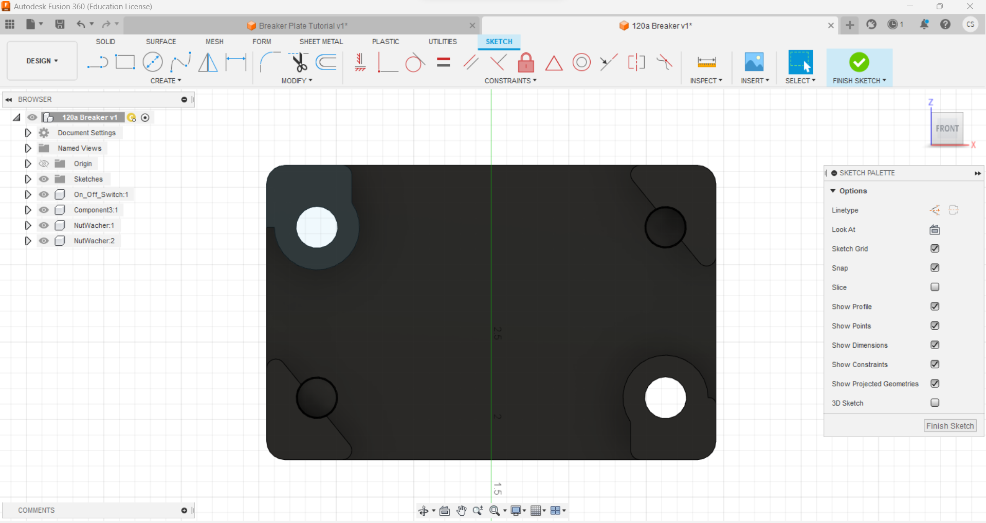
This is what the sketch should look like. The sketch is a 2D representation of one face of the 3D model. You can see the 3D model in the background. The sketch is on the “bottom face” of the 3D model.
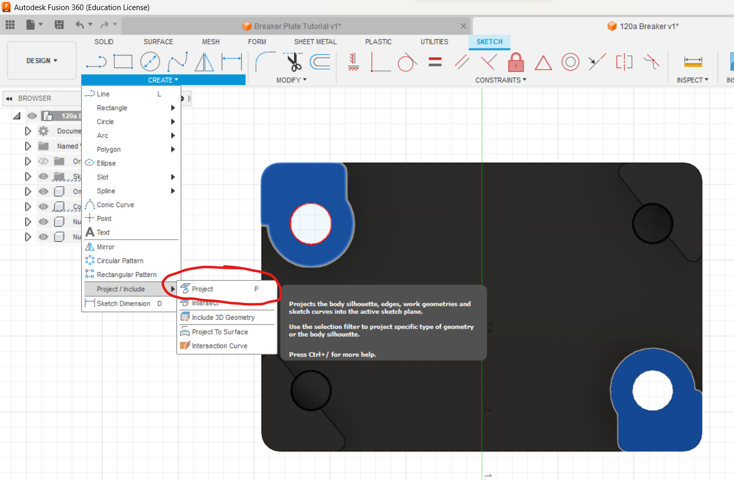
Step 3: Select both screws by Ctrl + Clicking on them. Then clicking on the drop down at the bottom of the create tab, select the “Project” option near the bottom of the list. This will project the edges and lines that make up our bolt holes onto the sketch. This is a very useful tool for making holes in plates and other parts from existing 3D models.
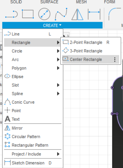
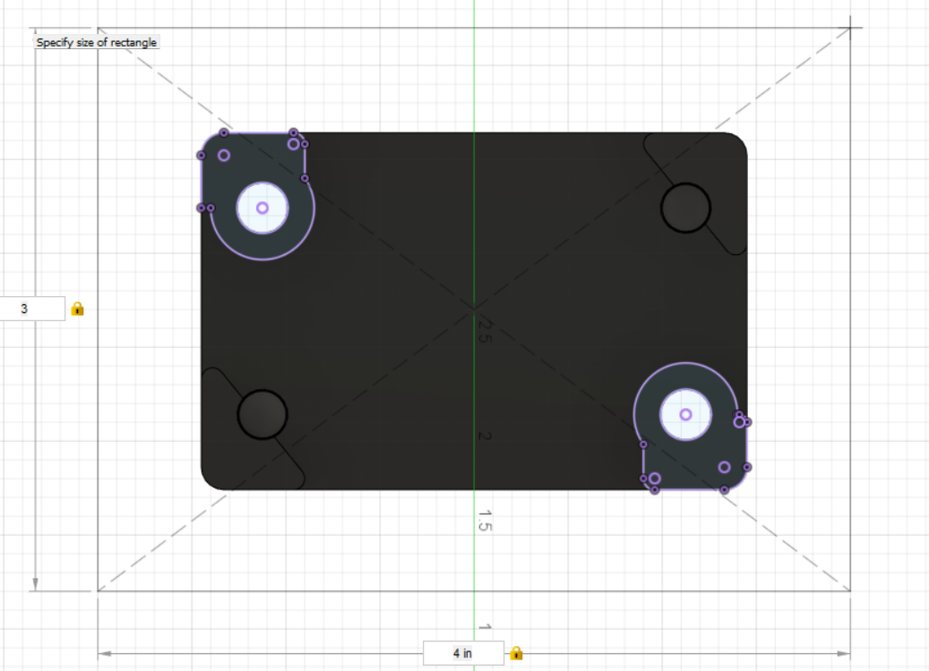
Step 4: Add a centered rectangle around the middle of the breaker. This is still part of the same sketch. For this short example you can just eyeball the center of the breaker. For more complex parts you can draw center lines or project more edges to get midpoints.
Step 5: The size of the plate should leave plenty of room for easy safety access and leaving enough room for bolts with even a really thin material.
Step 6: Finish the sketch by clicking the check mark at the top of the screen. This will take you back to the 3D design mode with your sketch visible. Now we can select the rectangle and extrude it out to make the plate. Note the extra pieces from the edges might get selected. You want the entire rectangle to be highlighted blue except for the holes. If you have extra pieces selected/unsleected, you can click on them with the Ctrl key held down to deselect/reselect them.
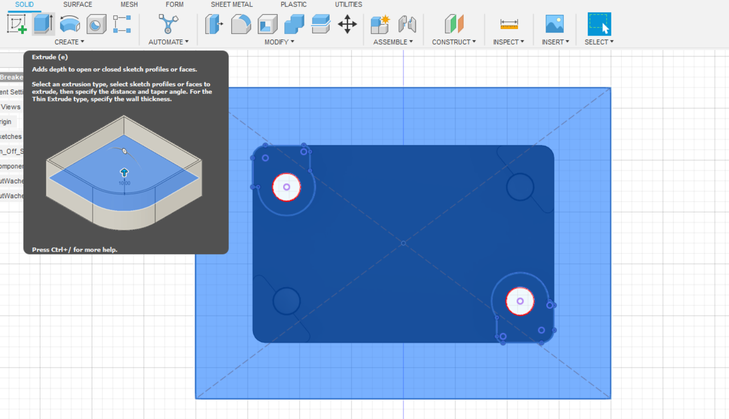
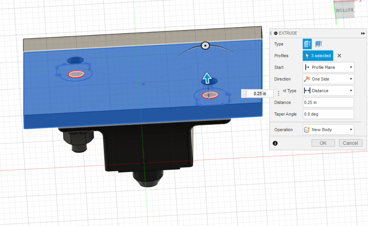
Step 7: With the sketch of the plate selected still, click the “Extrude” button. This will bring up the extrude dialog. You can rotate the 3d model to get a better view of the Distance Arrow. As you drag it up and down, you can see the plate get thicker and thinner. You can also type in a value in the box. I used 0.25 inches since this is a fairly thick size that works for even the weakest of materials. You also need to check the Operation section carefully. There are 5 options all with different purposes.
- New Body - This will create a new part in your design. This is useful if you want to make a new part from a sketch. You can also use this to make a new part from a 3D model. This is what we want to do here.
- New Component - This will create a new part in your design. This is useful if you want to make a new part from a sketch. You can also use this to make a new part from a 3D model. This is not what we want to do here.
- Cut - This will cut out the shape of the sketch from the part. This is useful if you want to make a hole in a part. This is not what we want to do here.
- Cut - This will cut out the shape of the sketch from the part. This is useful if you want to make a hole in a part. This is not what we want to do here.
- Join - This will add the shape of the sketch to the existing part part. This is not what we want to do here.
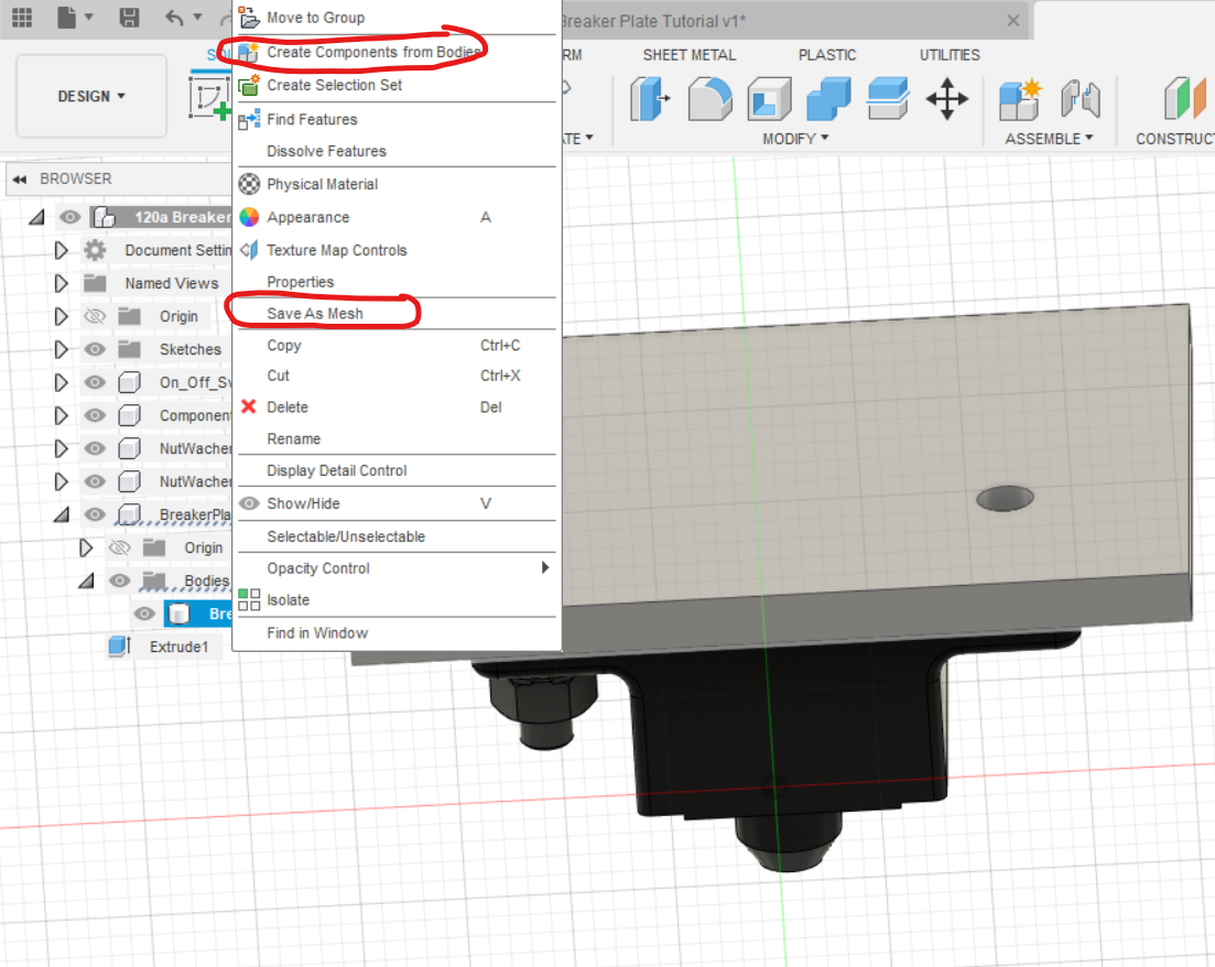
Step 8: Click the “OK” button to finish the extrusion. This will create a new part in your design. You can see the new part in the tree on the left side of the screen. You can also see the new part in the 3D view. The part will be under Bodies and given a default name. You can rename it by double clicking on it in the tree or right clicking on it and selecting “Rename”. You can also convert it to a component by right clicking on it and selecting “Create Component from Bodies”. Finally if you did turn it into a component you could now export it, send a copy to a team mate or even convert the body inside of our component into a STL to be 3d printed.
// TODO: Add a step for adding a hole for the battery positive lines.
!!!YOU JUST MADE YOUR FIRST PART IN FUSION 360!!!