3.1 What is Machining & Fabrication?
What is Machining?
Machining is the process of cutting, shaping, and finishing materials using a machine. In FRC machining is used to create parts for the robot. This can be done using a CNC machine, a 3D printer, or a manual mill or lathe. There are many different types of these machines, and each has its own advantages and disadvantages. This section will cover the basics of machining and how to use some standard machines. This is not an exhaustive list of all the machines that can be used in FRC, but it should give you a good starting point.
Machining is also a very old process. Don’t believe me? Check out this Machine shop at Greenfield Village in Michigan. This was a replica built in 1929 of the original 19th century Menlo park Machine Shop. The machines are driven by large generators, those then drive pulleys and belts that run all over the place to each machine. High tech stuff, but no 3d printers will be found here…

What is Milling?
Milling is the process of machining using rotary cutters to remove material from a workpiece. Milling covers a wide variety of different operations and machines, on scales from small individual parts to large, heavy-duty machines. The other term for a milling machine is a mill or some people will use a brand name like “Bridgeport”. All three variations refer to same machine. There are also several configurations for milling machines.
The Vertical Mill, which is the most common type of milling machine. This machine has a spindle that is parallel to the ground. The spindle can be extended or the table can be raised and lowered, giving the same effect, allowing plunge cuts and drilling. The table can also swivel left and right, allowing for angular cuts. The table can also be tilted in either direction, allowing for helical cuts. The most common type of vertical mill is the Bed Mill. This machine has a stationary spindle and the table is moved both perpendicular and parallel to the spindle axis to execute cuts.
In simpler terms, a vertical mill has a cutting tool that moves up and down only. The piece being cut is attached to a table or bed that moves in two directions, perpendicular and parallel to the cutting tool. The machines bed can be adjusted to do angled cuts or other types if it is a more advanced machine. It can make cuts in all directions, it can drill holes and it can be adjusted with dials to make very precise cuts.
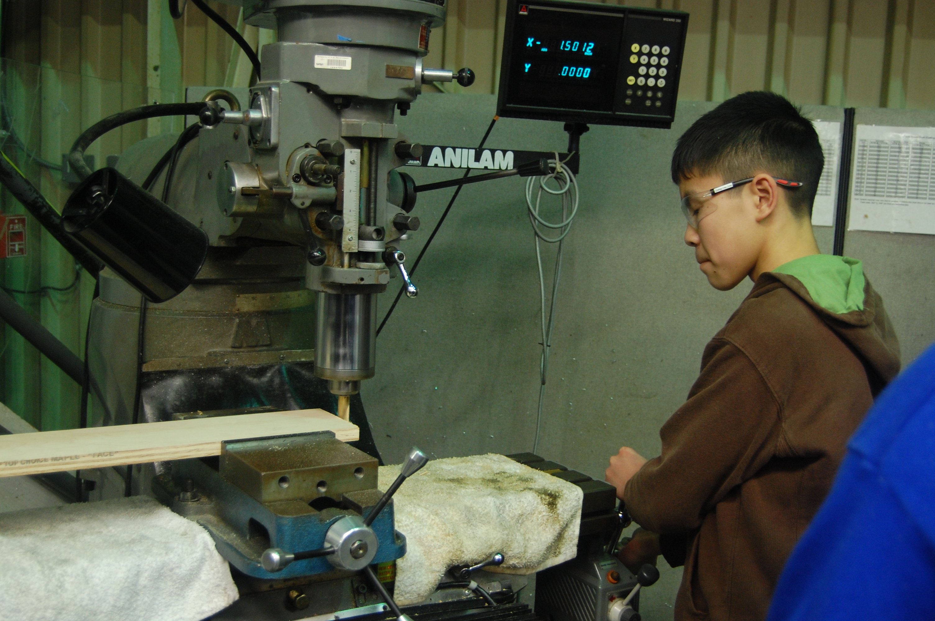
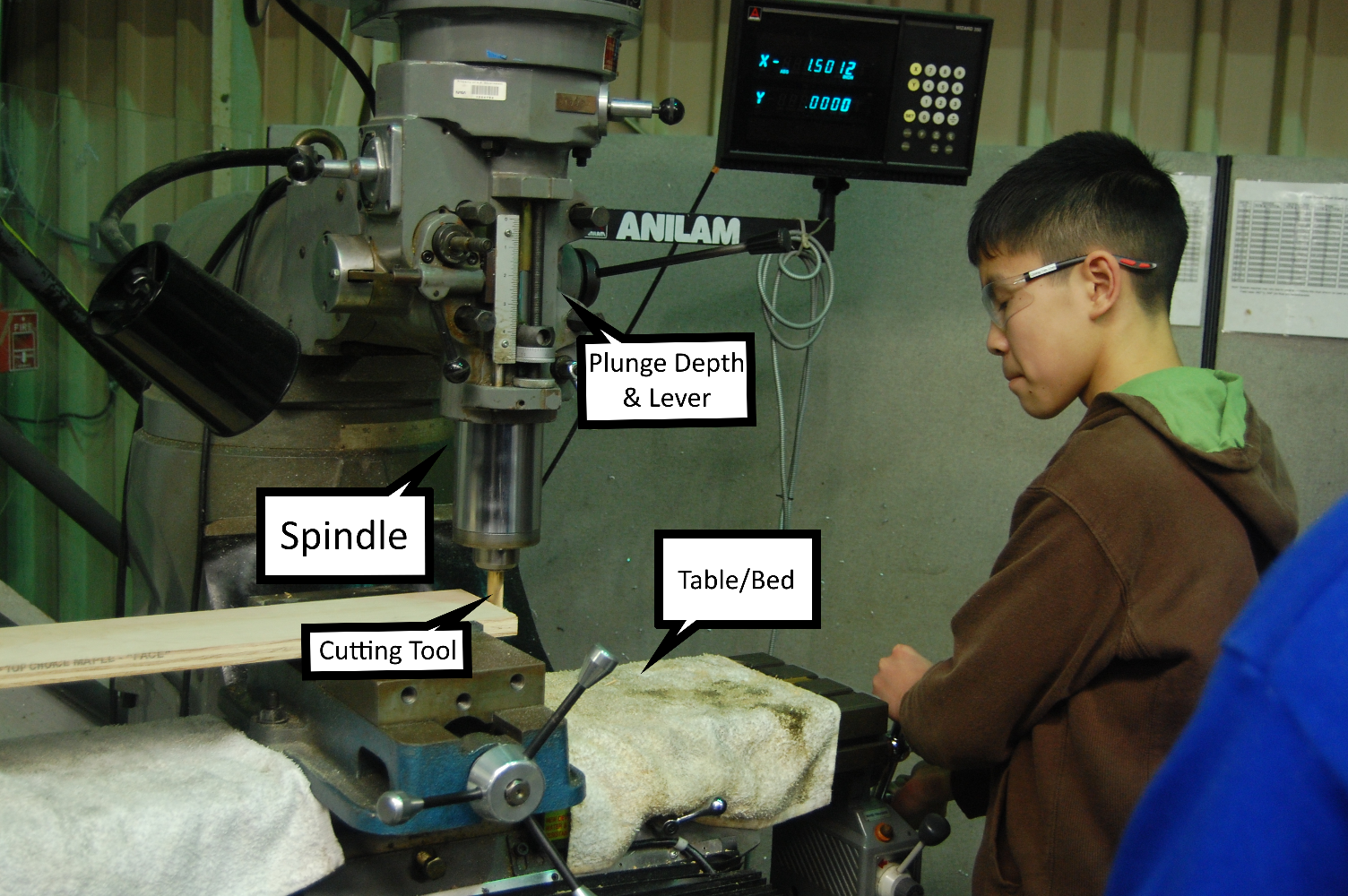 Picture from FRC 254 of a student using a vertical mill. original image source
What is Lathing?
Lathing is the process of cutting a piece of material to a specific shape and size using a lathe. A lathe is a machine that rotates the workpiece around an axis of rotation to perform various operations such as cutting, sanding, knurling, drilling, or deformation, with tools that are applied to the workpiece to create an object with symmetry about that axis. Lathes can commonly be used in woodworking, but these are NOT metal lathes. Metal lathes are used to cut metal and are much more powerful and hence dangerous. Things you can do on a wood lathe are not done the same way on a metal lathe.

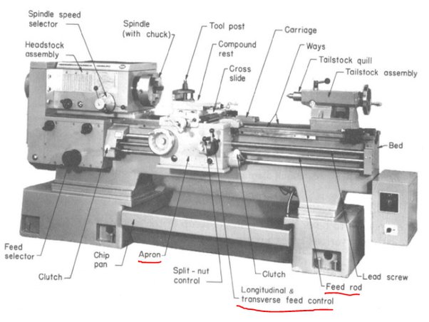
A lathe has several moving parts. The workpiece is held in place by a chuck or faceplate. The chuck is a device that holds the workpiece in place while it is being cut. The chuck is mounted onto a spindle. The spindle does not adjust in place and needs to hold your piece perfectly centered. Before ever powering on the machine you can check the spindle to make sure it is centered by turning by hand and looking for wobble on the stock piece. If you have a tail stock, you can use that to center the piece and hold it on both ends. The spindle is powered by a motor and some lathes have adjustable transmissions for tougher materials.
Then there is a tool post. Unlike a wood working lathe this is not meant for you to rest a hand cutter on. You must put the cutting tool in the holder and lock it in place. The cutting tool will experience a lot of force and will be pressed against the spinning stock. If the tool is not locked in place it will fly off and cause damage to the machine and possibly injury to the operator.
The movement in the x and y directions is done by two carriage systems and dials. Some machines also have motor driven carriages and can be programmed to do precise movements. The z axis is done by the tool holder. The tool holder is locked in place and the stock is moved in relation to the tool holder. This is done by moving the carriage systems and dials. The z axis is also done by the tool holder.
Finally the operator can then turn on the spindle. Most lathes support bi-directional control with a Double Pole Double Throw switch. Pulling the lever out away from its base and up will start the machine one way. Pulling the lever out away from its base and all the way down will start the machine the other way. The lever can be set back to the middle and released to stop it. You can also press the E-Stop, but only if it is an emergency. The E-Stop will stop the machine immediately and will not allow it to be restarted until the E-Stop is reset and it can damage the machine. Use the proper controls to stop the machine!
FRC 971 Lathe Training Manual
Team 971 has a great training manual for lathe safety and operation. It is a great resource for learning how to use a lathe. You can view it below or download it. The viewer doesn’t work on mobile devices.
What is a CNC Machine?
CNC or computer numerical control is a process that uses computers to control machine tools. CNC machines are used to make parts that would be difficult or impossible to make by hand. CNC machines are used in many different industries, including automotive, aerospace, and medical. CNC machines can make perfect circles, diagonals, and other shapes that are using two dials alone would be tough on a mill or lathe. If you want to do a thought exercise think about trying to write your name on an etch-a-sketch.

The dials on a mill can control one axis at a time. By turning both at once you can get a diagonal cut. This is not the same as a circle. A circle means you start one way, then have to reverse one dial, then the other, then the first one again, and then the second in a perfect, gradual pattern… It is tough and it’s why we use computers to do that gradient for us. CNC machines can also be programmed to do repetitive tasks. CNC machines use Gcode to control machines. It can control the axis movement speed, it can jog to a specific point, it can adjust the spindle speed, perform tool changes and more.
Notice how the term CNC can be applied to many different machines. Mills, Lathes, and even 3D printers can be CNC machines. CNC machines are not a specific type of machine, but a way of controlling a machine. This means if you understand the basics of CNC you can apply it to many different machines and tools. Gcode will change from machine to machine, but the basics of CNC operation will not!
What is a 3D Printer?
See, we pulled a sneaky on ya. 3D printers are not really “machining” in the traditional sense. Both milling and lathing are Subtractive manufacturing methods. They can only be used to remove material from a stock piece. 3D printing in its various forms is always an Additive manufacturing method. It can only be used to add material to a build plate. 3D printers are used to make parts that would be difficult or impossible for even Mills, lathes and molding to achieve. 3D printers can make parts that are very complex and have a lot of detail. 3D printing is much newer compared to milling and lathing and is still in its infancy.
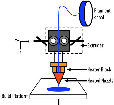
3D printers have several main parts that you should become familiar with. The easiest way to learn what they do is to explain how a printed part is made.
- A 3D model file is run through a slicing software. This software takes the 3D model and slices it into layers. Each layer is then converted into a series of Gcode commands. These commands are run by the printer and it will control the axis, tool end and other machine features.
- The printer will take in the file from the computer. This is done with an sd card, flash drive, direct connection or over wifi depending on your printer. The file will set the Build Plate and Extruder temperatures.
- The machine will start to heat up. Since 3D printing typically uses thermoplastics, the machine needs to heat up to the melting point of the plastic. The exact temperature depends on the plastic. PLA is typically 180-220C and ABS is typically 220-260C for your extruder. The build plate is typically 60-100C.
- Once the machine is heated up, the machine will move the Build Plate to the Home Position.
- The machine will then move the Extruder to the Home Position.
- Depending on your printer, the machine will then move the Build Plate to the start of the Gcodes first layer or it will move the Extruder to the start of the Gcodes first layer.
- The machine will then start to print the first layer. The Extruder will pull plastic from the spool and push it through the Extruder nozzle. The Extruder nozzle will then push the plastic onto the Build Plate. The Extruder will then move to the next point and repeat the process. This will continue until the layer is complete.
- Once the layer is complete, the machine will move up a set amount and repeat the process. This will continue until the part is complete.
An FRC specific resource about 3D printing was created by team 7528 and can be found here. They have sample lessons for slicing, troubleshooting, and more.
What is Fabrication?
Now that we have a basic understanding of machining, let’s talk about fabrication. Fabrication is the process of building something from raw materials or your newly machined parts. This can involve welding, cutting, bending, and more. Fabrication is a very broad term and can be used to describe many different processes. For the purposes of this guide, we will be focusing on the processes that are most commonly used in FRC.
What is Welding?

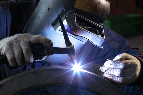
Ahem… Welding is the process of joining two pieces of metal together. There are many different types of welding, but the most common in FRC are MIG and TIG. MIG stands for Metal Inert Gas and TIG stands for Tungsten Inert Gas. Both of these processes use a wire electrode to create the weld. The wire is fed through a gun and the weld is created by melting the wire and the metal together. The difference between the two is the shielding gas. Both types of welding work on different materials. TIG welding is used on metals that are harder to weld. This includes aluminum, magnesium, and titanium. MIG welding is used on metals that are easier to weld. This includes steel, copper, and brass.
The arc is what melts the wire and the metal together and it is very very very bright, like YOU WILL GO BLIND bright. You should always have a welding helmet on and be behind a proper curtain if it is available. Just because you are protected with your helmet doesn’t mean the rest of your team is safe. Anyone who catches the arc even in a reflection can suffer blisters on their eyes and more. It is very important to be safe when welding.
The other kind of welding you could encounter outside of FRC is known as spot welding. This doesn’t pose a blinding risk, but is much more expensive. It also has very specific uses that aren’t really applicable to FRC. Spot welding is used to join two pieces of metal together by pressing two pieces together with an anvil and a punch. The punch is heated to a very high temperature and then pressed into the metal. This creates a weld that is very strong and can be used to join two pieces of metal together. This is used in the automotive industry to join car body panels together.
What is Cutting?
Cutting is the process of removing material from a piece of stock. While we already covered how to do this with machines like mills and lathes, this can also be done with hand tools like saws, angle grinders, and more. Cutting is a very broad term and can be used to describe many different processes. For the purposes of this guide, we will be focusing on the processes that are most commonly used in FRC.
What is a Saw?
A saw is a tool that is used to cut through materials. There are many different types of saws, but the most common in FRC are band saws and hacksaws. Band saws are used to cut through large pieces of metal. The blade is one continuous piece of metal that is wrapped around a wheel. The wheel is powered by a motor and the blade is pulled through the material. The blade is very sharp and can cut through material very quickly. Band saw blades will have different lengths, teeth counts and intended uses. A wood cutting blade will snap when and potentially injure someone if it is used on metal. A metal cutting blade will burn up wood pieces due to the higher friction and speed. It is important to use the correct blade for the material you are cutting.
Another common saw type is the table saw or chop saw. Chop saws can also be called mitre saws. These are very useful for cutting through materials at a specific angle. Both are also very dangerous and should only be used by people who have been trained on how to use them. These are used to cut through materials that are too large to fit on a band saw. These saws are very powerful and can be adjusted for blade depth, angle, and more. They are very dangerous and should only be used by people who have been trained on how to use them. All saws are dangerous, but these are especially dangerous for some reasons you might not expect. Pieces on a table saw can be flung off the blade and straight at people if it is let go of mid cut or ripped away from you. This can cause serious injury or death. It is very important to be safe when using a table saw.
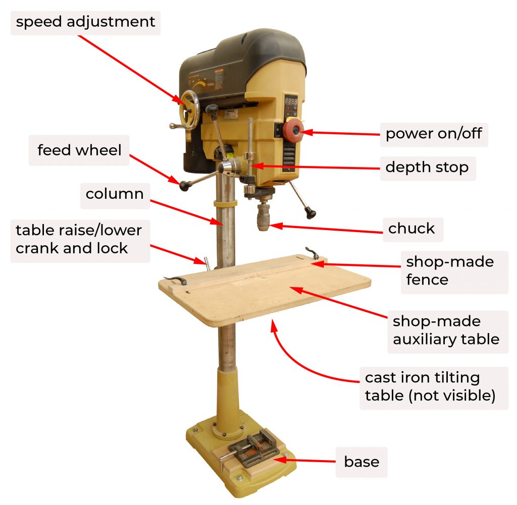
What is a Drill?
A drill is a tool that is used to make holes in materials. There are many different types of drills, but the most common in FRC are hand drills and drill presses. Hand drills can also be known as power screwdrivers that also double as a cordless drill. Many brands exist out there, but they all are essentially the same. They have a rechargeable battery, a motor, and a chuck. The chuck is what holds the drill bit. The drill bit is what actually makes the hole. The motor spins the drill bit and the battery powers the motor. The drill bit is very sharp and can cut through material very quickly. The drill bit will have different lengths, diameters and intended uses. A wood cutting bit will snap when and potentially injure someone if it is used on metal. If you try to use a drill bit for milling by mistake it can bend or snap the bit, even if its a metal cutting bit. Mr. Siefen has seen this done far too many times… It is important to use the correct bit for the material you are drilling.
Drill presses work in much the same way, but they have a bed, possibly a vise and adjustable height. The drill bit is held in place by a chuck and that is attached to a spindle. The spindle can be plunged down into your stock material to drill a hole. The bed and vise can be brought up and down or turned to bring it in range of the drill bit and to line up the bit in the right spot on the material. Drill presses are very useful for drilling holes in materials that are too large to fit on a hand drill. These are also much more accurate. hand drills are controlled by your hands and not guaranteed to be straight or in the right spot. Drill presses are much more accurate and can be adjusted for depth, angle, and more. They are very dangerous and should only be used by people who have been trained on how to use them. If you have an adjustable speed drill press, or an oscillating drill press, you should be very careful when using changing the belts. Unplug the machine and ensure that the belt is not moving before you change it. If you are not sure how to change the belt, ask someone who does know how to do it.
What is a Grinder?
No, not the sandwich. A grinder is a tool that is used to grind down materials. There are many different types of grinders, but the most common in FRC are angle grinders and bench grinders. Angle grinders are handheld grinders that are used to grind down materials. They can be electrically driven, but are most commonly pneumatic. The grinding heads will come in a variety of shapes and sizes. The most common is a disc grinder. The disc is very rough and will grind down material very quickly. The disc spins at very high speeds and should be inspected before use. If the disc is cracked or damaged in any way, it should be replaced. Dremels are NOT grinders. They are rotary tools and should not be used to grind down materials. They are not designed to handle the forces that a grinder can put out. They will burn out and waste your time.
Some other grinding types are flap wheels, wire wheels, and more. These all have very specific uses. Flap wheels are very useful for grinding down material, but not quickly. The flaps can be pushed inside of pieces or used to evenly remove material in round holes. Wire wheels are very useful for removing rust and paint from metal. They are very dangerous and should only be used by people who have been trained on how to use them and wearing the appropriate PPE like a ventilation mask.
A bench grinder is a stationary grinder that is used to grind down materials. They are very similar to angle grinders, but will typically have removable wheels. One side is usually a grinding wheel and the other side is usually a wire wheel. These will have a very high RPM and MUST be attached down to a bench or table. They can be used to sharpen drill bits, deburr metal, and more.
What is Bending?
Bending is the process of bending a piece of material. This can be done with machines like a press brake or a hydraulic press. It can also be done with hand tools like a vise, a hammer, and more. Bending is a very broad term and can be used to describe many different processes. For the purposes of this guide, we will be focusing on the processes that are most commonly used in FRC.
What is a Press Brake?
A brake press is a machine that is used to bend metal. A piece of sheet metal is placed onto the bed. There is a die (the under side) and a punch (the top side). The die is what the piece of metal will be bent around. The punch is what will push the piece of metal into the die. There is also a back gauge that can be adjusted to control how far the piece of metal is pushed into the die. For most FRC uses a manual brake can bend 6061 aluminum. A manual brake is not as powerful as a hydraulic press, but it is much cheaper. Team 217, the Thunder Chickens use metal brakes for their designs. Speaking with them at MCC 2022 taught me so much and they were very helpful. Even back in 2007 they were using this technique to make custom chassis designs.

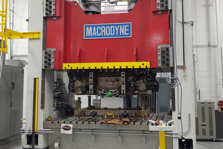
What is a Hydraulic Press?
A hydraulic press is a machine that is used to bend metal. Just like the manual press brake, a piece of sheet metal is placed onto the bed. There is a die (the under side) and a punch (the top side). The die is what the piece of metal will be bent around. The punch is what will push the piece of metal into the die. The hydraulics however make it much more powerful and much more dangerous. The hydraulic press can bend and punch much thicker materials than a manual press brake. Materials as thick as your arm. Many presses require two operators to enable the downward motion, or both hands of one operator on two buttons at once to ensure they are not accidentally pressed. The depth and pressure of the pressing is controlled from a control panel. A hydraulic press can be very dangerous and should only be used by people who have been trained on how to use them and wearing the appropriate PPE.