5.4 How to Setup a Pneumatic System
Setting up a pneumatic system can be a daunting task. This section will cover the basics of setting up a pneumatic system. It will cover the basics of the components and how to connect them. It will also cover the basics of how to setup the compressor and the PCM and how to test the system.
Gatherings the Components
The first step in setting up a pneumatic system is to gather the components. The components are listed below:
- Compressor
- Release Valve
- Pressure Switch
- Pressure Gauge x2
- Manual Release Valve
- Air Tank
- Pressure Regulator
- Solenoid
- Pneumatic Hose
- Fittings & Connectors
- Pneumatic Control Module (PCM) or Pneumatic Control Hub (PCH)
Compressor
The air compressor is the heart of the pneumatic system. It is the device that compresses the air and stores it in the air tank. The compressor is connected to the PCM and the PCM controls the compressor. Compressors will automatically run unless the pressure switch is above the set pressure limit. The compressor can also be manually turned on and off from the robot code. The PCM and the compressor are connected with a 12V power cable. The red and black wire spots are marked on the PCM or Hub.
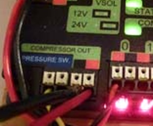 This is a close up of the wiring for the compressor and the PCM.
Release Valve
The release valve is used to release the pressure from the system. The release valve is a non-electrical system that will manually go off if the pressure switch is overridden. All excess air pressure over 125psi will be released automatically when tuned properly. This is checked and tested by the inspectors.Don’t wait until competition to find out that your release valve is not working. Test it before you get to competition and while initially putting the system together.
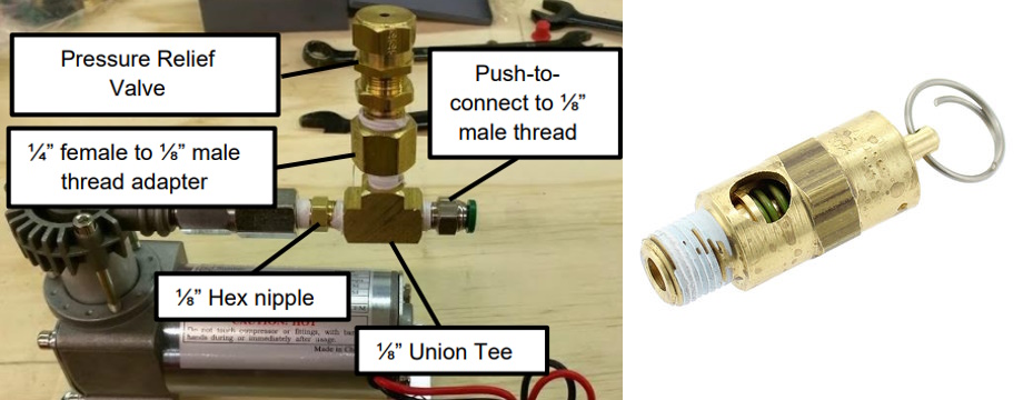 This is a close up of the release valve.
Pressure Switch
The pressure switch is used to control the compressor. The pressure switch is connected to the PCM next the compressor. The pressure switch is used to turn the compressor on and off. The pressure switches’ air port is connected to the system on the high pressure side. By default the pressure switch is set to 120 psi. The pressure switch should NOT be adjusted. This is checked and tested by the inspectors. If the pressure switch is adjusted, the team will have to replace it with a stock one.
Pressure Gauge (High Side)
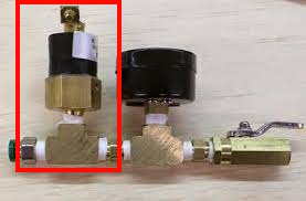
Pressure guages help us (humans) see the current PSI of the system using an analog (not electrical analog) dial indicator. The pressure gauge is connected to the system on the high pressure side. The best way to be able to use it is to put it somewhere that you can see it. Many teams will connect a T fitting to the high pressure side and then connect the pressure gauge and the pressure switch to the T-fitting(s). This allows the pressure gauge to be easily seen and the pressure switch to be easily connected. If it is also located near the manual release valve, it can be used to check the pressure before releasing the valve.
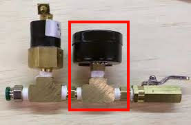 This is a close up of the tubing and port connection for the pressure gauge.
Manual Release Valve
The manual release valve is used to release the pressure from the system. The manual release valve is a non-electrical system that will manually go off if a lever is pulled or a ball valve is turned. All air pressure from the system will be released when the valve is opened. This is checked and tested by the inspectors. This is a safety feature that is required on all FRC robots that store compressed air. It should be easily accessible and easy to use after a match has ended.
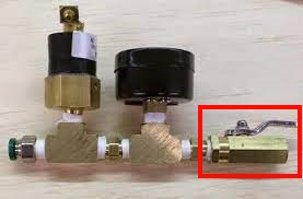 This is a close up of the manual release valve.
Air Tank
The air tank(s) are also located on the high side of the system. The tanks with either have a 1/4" NPT port or a threaded port to attach your own connectors. Whenever you are adding a new fitting, or removing an existing one, on a tank you need to:
- Make sure the tank is empty
- Wrap the threads with Teflon tape
- Tighten the fitting (Don’t over tighten)
- Check for leaks with a low pressure fill test before adding to your full system
- Add soap and water to an old spray bottle and spray the fittings to check for leaks. If you see bubbles, you have a leak.
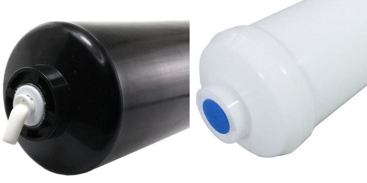 This is a close up of the tubing and port connection for the air tank.
Pressure Regulator
The pressure regulator is what sets the PSI level for the low side of the system. Best practice is to set the pressure regulator to 60 psi. Solenoids can operate at more or less pressure by adjusting the regulator. Most regulators have a knob that can be turned to adjust the pressure. In order to adjust it you have to first pull up on the knob and then turn it. Clockwise increases the pressure and counter-clockwise decreases the pressure. The pressure regulator has an input side and an output side. Make sure which is which! The input side is sometimes marked with an triangle like in the picture below. The input side is the side that is connected to the high pressure side of the system. The output side is the side that is connected to the low pressure side of the system.
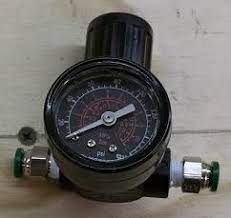 This is a close up of a pressure regulator.
Solenoid
In order to control the flow of air we use a special type of valve called a solenoid. Solenoids are controlled by the PCM or PCH. The solenoid has a port on the input side and a port on the output side. The PCM or PCH will send a signal to the solenoid to open or close the valve. The solenoid will open or close the valve depending on the signal it receives. The red and black wire spots are marked on the PCM or Hub. The block underneath the solenoid is called a manifold. The manifold is used to connect the air ports to the solenoid.
 This is a close up of a solenoid and manifold.
Pneumatic Hose
There are many vendors that sell the proper hose for pneumatic systems. The hose is measured by the inside diameter (ID) and the outside diameter (OD). The OD is the size of the hose and the ID is the size of the port that it connects to. The OD of the hose should be 1/4" and the ID of the port should be 1/4". The hose should be flexible and not kink easily. The hose should be able to withstand the pressure of the system (125 psi MAX). Below is a table with the different types of hose and their pressure ratings with a column for the vendor with a link to the product page:
| Vendor | Hose Type | Pressure Rating | Link |
|---|---|---|---|
| McMaster-Carr | Polyurethane | 150 PSI | Link |
| AndyMark | Polyurethane | 125 PSI | Link |
| AndyMark | Polyurethane | 116 Official/125 Tested PSI | Link |
| VEX | Polyurethane | Not Listed PSI | Link |
Fittings & Connectors
Fittings and connectors can vary wildly from vendor to vendor. The fittings and connectors should be able to withstand the pressure of the system (125 psi MAX). Below is a table with the different types of fittings and connectors and their pressure ratings with a column for the vendor with a link to the product page:
| Vendor | Fitting Type | Pressure Rating | Link |
|---|---|---|---|
| McMaster-Carr | Push to Connect | 150 PSI | Link |
| AndyMark | Various | 125 PSI | Link |
| VEX | Push to Connect | Not Listed PSI | Link |
Below is a chart with some images of the different types of fittings and connectors. Please note teams will have different names they use as casual names for the fittings and connectors. The names in the chart are the official names for the fittings and connectors:
| Fitting/Connector | Image | Description |
|---|---|---|
| Push to Connect Threaded 1/4" NPT port |  |
Push to Connect fittings are used to connect the hose to the ports. They are easy to use and can be used with a wide variety of hose. |
| Push to Connect to 1/4" NPT |  |
Push to Connect to 1/4" NPT fittings are used to connect the hose to the ports. They are easy to use and can be used with a wide variety of hoses and fittings between the various styles of connectors. |
| Push to Connect (T Connector) |  |
This type of connector splits off into 3 ends that can have Push to Connect ends |
| Threaded 1/4" NPT (T Connector) |  |
This type of connector splits off into 3 ends that can accept 1/4" NPT fittings. |
| 1/4" NPT |  |
1/4" NPT fittings are used to connect the hose to the ports. They are easy to use and can be used with a wide variety of hose. |
| 1/4" NPT to 1/4" NPT |  |
1/4" NPT to 1/4" NPT fittings are used to connect the hose to the ports. They are easy to use and can be used with a wide variety of hose. |
| 1/4" NPT to 1/4" NPT to 1/4" NPT (T Connector) |  |
1/4" NPT to 1/4" NPT to 1/4" NPT fittings are used to connect the hose to the ports. They are easy to use and can be used with a wide variety of hose. |
There are also smaller types of fittings that are typically used for the solenoids. These are typically 1/8" NPT fittings. These are typically used for the solenoids and are not typically used for the main air lines. They can have a smaller diameter hose and are typically used only on the low pressure side of the system.
Using all of the combinations of fittings and connectors, you can create a wide variety of pneumatic systems. Your team will need to figure out what works best for your team’s unique hardware setup. Below are some example pneumatic fitting images in the context of FRC to help you get started:
 This is an example of “The Fitting Type” connecting “__ & __ "
 This is an example of “The Fitting Type” connecting “__ & __ "
 This is an example of “The Fitting Type” connecting “__ & __ "
 This is an example of “The Fitting Type” connecting “__ & __ "
 This is an example of “The Fitting Type” connecting “__ & __ "
Connecting the PCM or PCH to the RoboRIO and PDP
Finally we can go through the process of connecting up the PCM or PCH to the RoboRIO and PDP. The PCM or PCH is connected to the RoboRIO and PDP using a 2 wire daisy chain commonly used in FRC called CAN. CAN or Controller Area Network is a serial bus that is used to connect multiple devices together. The RoboRIO and PDP are both CAN devices and the PCM or PCH is also a CAN device. You can support up to 63 CAN devices on a single CAN bus. most devices in the system will have 2 seperate Channels for in and out, except the Roborio which is a special case. The Roborio is always the starting point of your CAN connection in FRC.
In logical order the wiring for CAN should always go like this: RoboRIO -> (Other CAN devices) -> PCM or PCH -> (Other CAN devices) -> PDP (have the termimating resistor jumper active on the PDP)
In a system with no other CAN components, like CAN motor controllers or sensors, the PCM or PCH is connected to the RoboRIO and PDP using the following diagram:
 This is a close up of the PCM or PCH to the RoboRIO and PDP. Note: The process is the same for both! This diagram was made in Fritzing. I dont have a PCH fritzings part so I used the PCM part. The PCH is the same as the PCM for CAN connection.
The power connections for the PCM or PCH are as follows:
Battery Positive -> Breaker -> PDP Positive -> Roborio and PCM/PCH Positive through their dedicated and marked ports
Battery Negative -> PDP Negative -> Roborio and PCM/PCH Negative through their dedicated and marked ports